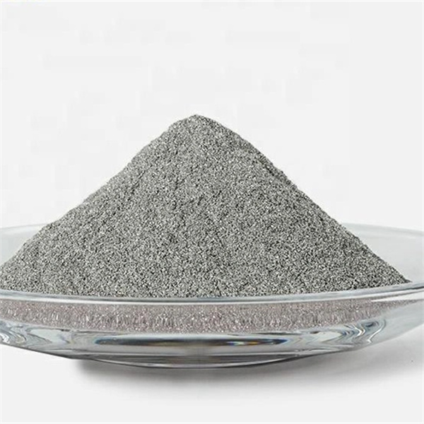
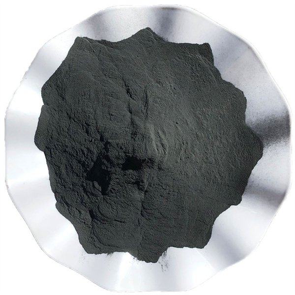
Metal injection molding (MIM) is a manufacturing process used to produce small, complex metal parts with tight tolerances. MIM combines the versatility of plastic injection molding with the strength and integrity of machined metals. This article provides a detailed overview of MIM technology, applications, equipment, process, design considerations, and more.
Overview of metal injection molding
Metal injection molding is a powder metallurgy process that enables high volume production of small, precision metal components using injection molding techniques.
How MIM Works
The MIM process involves mixing fine metal powder with a binder material to create a feedstock that can be injected into molds. The molded parts, known as green parts, are then sintered to remove the binder and consolidate the metal powder into a solid structure. The basic steps are:
- Mixing – Fine metallic powder is blended with binders to create a homogeneous feedstock
- Injection Molding – The feedstock is melted and injected into the mold to form green parts
- Debinding – The binder is removed through solvent, thermal, or catalytic debinding
- Sintering – The debound parts are sintered to densify and strengthen the metal structure
- Secondary Operations – Additional finishing steps like machining, drilling, tapping etc.
Advantages of MIM
MIM offers several benefits compared to other manufacturing techniques:
- High volume production with low cost per part
- Complex geometries with tight tolerances
- Variety of materials like stainless steel, titanium, tungsten, cobalt chromium etc.
- Minimal scrap losses and material waste
- Near net-shape fabrication reducing machining
- Small part sizes from 0.005 lbs to 0.5 lbs
- Parts consolidation by combining assemblies
- Smooth surfaces and good finish
Limitations of MIM
Some limitations of metal injection molding include:
- High startup and tooling costs
- Limited size range for parts
- Specialized equipment required
- Multi-step process with slower production
- Dimensional limitations based on powder characteristics
- Restrictions on part geometry based on powder flow
Applications of MIM
MIM is widely used to manufacture small, complex parts with tight tolerances across industries like:
- Medical – orthopedic implants, dental implants, surgical instruments
- Automotive – engine components, valves, gears
- Aerospace – turbine blades, impellers, nozzles
- Electronics – connectors, micro gears, shielding
- Firearms – triggers, hammers, safeties
- Watches – watch cases, bracelets, crown
- Industrial – knobs, fasteners, cutting tools
MIM competes against other processes like investment casting, machining, and stamping for metal part production.

metal injection molding Equipment Guide
Specialized equipment is required for each stage of the MIM process. Here are the key MIM equipment types:
| Equipment | Function |
|---|---|
| Powder feeders | Accurately meter fine powders |
| Mixers | Homogeneously blend powder and binder |
| Granulators | Form feedstock into granules for molding |
| Injection molding machines | Mold the feedstock into required shapes |
| Debinding furnaces | Remove binder from molded parts |
| Sintering furnaces | Densify and strengthen metal structure |
| Grinding machines | Remove gates, runners and smooth surfaces |
| Machining centers | Drill, turn, mill features into sintered parts |
Advanced automation, handling systems, and controls are used to integrate the process and maximize productivity. The equipment must be carefully selected based on factors like material, part size, production volume and quality requirements.
metal injection molding Process Step-by-Step
MIM processing involves multiple steps to transform fine metal powder into fully dense end-use components.
Step 1 – Mixing
- The metal powder and binder are thoroughly blended in a mixer to produce a homogeneous feedstock
- Powder particle size, shape, distribution impact moldability and sintering
- Binders provide flow and adhesion during injection molding
- Waxes, thermoplastics like PP, PE, PVC, and polymers used as binders
- Mixing done using sigma blade, Z-blade, double planetary mixers
Step 2 – Granulation
- The feedstock mixture is granulated into small pellets for injection molding
- Improves material flow and prevents segregation in the barrel
- Granulators use rotating blades to cut feedstock into uniform granules
- Granule shape and size affects packing density and moldability
Step 3 – Injection Molding
- The feedstock granules are molded into the required part shape and size
- Uses modified injection molding machines with controlled temperature and pressure
- Important to optimize molding parameters to minimize defects
- As-molded parts called green parts have imparted shape but no strength
Step 4 – Debinding
- The binder is extracted from the green parts through solvent, thermal or catalytic means
- Solvent debinding uses capillary action to dissolve the binder
- Thermal debinding decomposes the binder in a furnace
- Catalytic debinding accelerates binder removal with a catalyst
- Debinding creates brown parts with a porous structure of metal particles
Step 5 – Sintering
- Brown parts are sintered in a controlled atmosphere furnace
- Bonds between metal particles are formed through diffusion and mass transport
- Near full density up to 96-99% achieved during sintering
- Atmosphere, temperature, time optimized to avoid defects
- Sintering shrinkage accounted for during molding
Step 6 – Secondary Operations
- Additional metalworking steps like annealing, machining, drilling, plating
- Annealing relieves internal stresses from sintering
- CNC machining removes sprues, smoothens surfaces, adds features
- Plating and painting applied for enhancement or corrosion protection
The MIM process enables complex, high precision metal parts by combining the advantages of plastic injection molding and powder metallurgy.
Design Considerations for MIM Parts
MIM enables geometric freedoms not possible with machining, but requires certain design considerations:
- Wall thickness – Typical range of 0.3 – 4.0 mm with some powders supporting up to 6mm walls
- Surface finish – Smoother finish than casting but not as fine as machining; Ra value of 1 – 4 μm is typical for MIM
- Dimensional tolerances – ±0.1% to ±0.5% based on part geometry with some micron level precision possible
- Density – Full density up to 99% can be attained with optimized sintering
- Geometry – Avoiding trapped powders and allowing binder escape is critical
- Draft angles – Tapered walls with 1-3° draft angles to ease part ejection
- Radii and fillets – Gradual transitions preferred over sharp corners
- Holes and cavities – Minimum diameters of 0.25 – 0.5mm for through holes
- Threads – Can be molded but often machined after sintering for better accuracy
- Surface details – Limit fine details to reduce mold wear; post-molding processes can enhance
MIM design should focus on geometry that maximizes performance rather than ease of fabrication. The process enables consolidation of multi-part assemblies into one part with significant cost and weight savings.
Materials Used in Metal Injection Molding
MIM can produce parts from a wide range of metals, alloys, and ceramics in diverse industries.
| Material | Applications | Properties |
|---|---|---|
| Stainless steel | Medical, firearms, marine | Corrosion resistance, strength |
| Low alloy steel | Automotive, industrial | Magnetic response, machinability |
| Soft magnetic alloys | Sensors, actuators | High permeability |
| Hard metal alloys | Cutting tools | Wear resistance, hardness |
| Copper alloys | Electronics, thermal | Electrical conductivity |
| Aluminum alloys | Electrical, thermal | Lightweight, conductivity |
| Titanium alloys | Aerospace, automotive | Strength, biocompatibility |
| Tungsten alloys | Radiation shielding | High density |
| Cermets | Electronics, optics | Oxidation resistance |
Factors like part function, cost, post-processing steps, and alloy compatibility determine the ideal MIM material choice.
MIM Suppliers and Equipment Manufacturers
Many companies offer MIM materials, services, production, and equipment globally. Here are some of the major MIM suppliers across the value chain:
| Company | Products/Services |
|---|---|
| BASF | Feedstocks, binders |
| Sandvik Osprey | Metal powders |
| Höganäs | Metal powders |
| CNPC Powder | Metal powders |
| Indo-Mim | MIM products, services |
| MPP | MIM products, services |
| ARC Group | MIM products, services |
| Atlas Pressed Metals | MIM parts production |
| Epson Atmix | MIM equipment |
| Milacron | Injection molding machines |
| Elnik | Sintering furnaces |
| TCN | Debinding, sintering furnaces |
There are also many smaller regional players involved across the MIM supply chain. End-users looking to adopt MIM can partner with material suppliers and contract manufacturers depending on capabilities required.
Cost Analysis of MIM Parts vs. Alternatives
Here is a comparison of estimated costs for producing 1000 parts using different manufacturing processes:
| Process | Set Up Costs | Machine Costs | Tooling Costs | Part Cost | Total (1000 parts) |
|---|---|---|---|---|---|
| CNC Machining | Low | $100,000 | $2,000 | $50 | $52,000 |
| Investment Casting | High | $500,000 | $40,000 | $20 | $60,000 |
| Metal Injection Molding | High | $750,000 | $100,000 | $15 | $115,000 |
| Stamping | High | $1,000,000 | $150,000 | $10 | $160,000 |
- CNC machining has low volumes, high part costs, limited complexity
- Investment casting is better for volumes up to 10,000 units
- MIM has advantage for mid to high volumes with complex geometry
- Stamping has very high tooling costs but lowest part price in high volumes above 100k parts
The crossover point where MIM becomes more economical than other processes depends on volumes, complexity, and size.
Choosing a MIM Supplier or Partner
Selecting a competent MIM supplier or production partner is crucial for cost-effective parts production. Here are key considerations:
- Technical expertise – Prior experience with similar MIM parts, materials, industry
- Quality systems – ISO 9001 certification, quality control practices
- Production capacity – Ability to meet present and future volume requirements
- Secondary processes – Machining, stamping, plating, painting capabilities
- Part optimization – Design for MIM support to maximize benefits
- Prototyping – Rapid prototyping services to validate designs
- Tooling capabilities – Inhouse tooling design and fabrication preferred
- Raw material access – Established supply channels for feedstocks
- R&D capabilities – Ongoing R&D in advanced materials and manufacturing techniques
- Customer focus – Responsiveness to needs and collaboration approach
- Cost structure – Pricing model and competitiveness for forecasted volumes
- Logistics – Ability to deliver parts reliably while meeting lead time requirements
Prioritizing these factors will help identify the right strategic MIM partner for a particular application.
Installing MIM Equipment
For companies installing MIM capabilities in-house, proper equipment installation is vital. Here are key considerations:
- Floor space of about 2000 – 5000 sq ft needed for MIM line
- Stable power supply with 200-600 kVA capacity required
- Compressed air lines rated for 100 psi pressure
- Exhaust ventilation for heat, emissions, and dust collection
- Utilities like nitrogen, process water, and gas supplies
- Temperature and humidity control of around 20±3 °C, 50±20%
- Mezzanines, platforms for installing ancillary equipment
- Material handling systems like hoists, forklifts, bins
- Control room, computer systems for monitoring
- Staff training on process safety and equipment operation
- Process simulations, test runs to validate installation
- Calibration and preventive maintenance schedules
Adequate space, utilities, and controlled conditions are essential for smooth MIM equipment operation. Thorough testing and training prepares for real production.
MIM Equipment Maintenance
Consistent maintenance improves uptime and performance of MIM production equipment. Key aspects:
- Documented preventive maintenance schedule for each machine
- Daily cleanup of material spills, leaks, dust, debris
- Checking fluid levels, leaks, unusual noises, vibrations
- Monitoring pressures, temperatures, power consumption
- Testing of heating, cooling, and control systems
- Replacement of wear parts like screens, screws, barrels
- Inspections for component fatigue, damage, alignment
- Regular rebuilds and overhauls based on operating hours
- Tracking of maintenance logs for analysis
- Storage of spare parts inventory for critical components
- Training on proper equipment operation and safety
- Timely service and support from equipment vendors
Well-trained staff and collaboration with equipment vendors helps maximize productivity of MIM equipment while minimizing downtime.
Metal Injection Molding Simulation Software
Simulation software is used to digitally model the MIM process before actual production. Benefits include:
- Prediction of mold filling patterns and optimization of gate locations
- Identifying weld lines and air traps to prevent defects
- Studying thermal gradients and solidification in complex geometries
- Simulating debinding and sintering profile effects on final shape
- Validating tooling designs before fabrication
- Reducing trial costs through virtual prototyping
- Training personnel through visual representations
Some commercial MIM simulation packages include:
- MIMSIM – Integrated simulation for molding through sintering
- Sigma Soft – 3D FEM analysis of mold filling and distortion
- Netzsch MIMPre – Modeling of MIM feedstocks rheological properties
- Simufact Additive – Multiphysics simulation of AM processes
- EOS PSW – Simulation focused on sintering and heat treatment
Using MIM software improves process consistency, optimizes part quality, and reduces physical prototyping costs. An integrated simulation-to-production workflow is preferred.
Troubleshooting Common MIM Defects
Some typical defects in MIM parts and potential root causes are:
| Defect | Causes |
|---|---|
| Short shots | Low injection pressure, premature solidification |
| Flash | Overpacked molds, mold damage |
| Warpage | Non-uniform cooling, binder issues |
| Cracks | Fast sintering, high binder content |
| Porosity | Poor homogenization, trapped gases |
| Contamination | Cross-contamination, furnace atmosphere |
| Dimensional variations | Feedstock issues, mold wear, shrinkage |
| Surface defects | Gas porosity, liquid metal embrittlement |
| Inclusions | Contaminated raw materials, nozzle clogs |
A systematic defect analysis methodology should be used to isolate process parameters causing defects and undertake corrective actions like adjusting feedstock formulation, molding parameters, debinding and sintering profiles.
Advantages of MIM Technology
MIM offers significant advantages over other metal parts production approaches:
- Complexity – Intricate 3D geometries possible, consolidates assemblies
- Consistency – Highly repeatable process with low part variance
- Efficiency – Near net shape fabrication with less raw material waste
- Automation – Highly automated process reduces labor
- Flexibility – Broad range of materials like metals, ceramics, composites
- Quality – Good surface finish and mechanical properties
- Productivity – High volume output with low cost per part
- Miniaturization – Micro-components with details down to 10 μm
- Sustainability – Energy efficiency compared to machining
- Cost – Lower total cost for mid to high production volumes
The unique capabilities of MIM are driving adoption across diverse industries like automotive, aerospace, medical, and electronics.
Limitations of Metal Injection Molding
Despite many benefits, MIM has certain limitations:
- High initial tooling investment
- Limited size range typically under 65 grams
- Lower accuracy than CNC machining
- Porosity risks requiring process controls
- Restricted material choices based on powder characteristics
- Safety hazards of fine powders
- Part geometry constraints related to moldability
- Potential lot-to-lot variability
- Lower mechanical properties than wrought materials
- Limited production of prototypes in lower volumes
- Requirement for secondary machining in many applications
- Specialized equipment and trained operators needed
For very high precision or larger metal parts produced in low volumes, other processes may be better suited than MIM.

The Future of Metal Injection Molding
MIM is expected to see strong continued growth as technology and materials continue improving:
- New binder systems to improve moldability and green strength
- Novel feedstock formulations using nanocomposites
- Larger sized parts exceeding current limits
- Increased adoption of ceramics and tungsten alloys
- Strong demand growth in medical, electronic sectors
- Use of additive manufacturing to make MIM tooling
- Automation using robotics and Industry 4.0 integration
- More applications in extreme environments
- Convergence with metal 3D printing using bound metal deposition
With increased R&D and easier adoption, MIM usage will grow rapidly across diverse applications in coming years.


